Posts

BARREL TEMPERATURE

Image
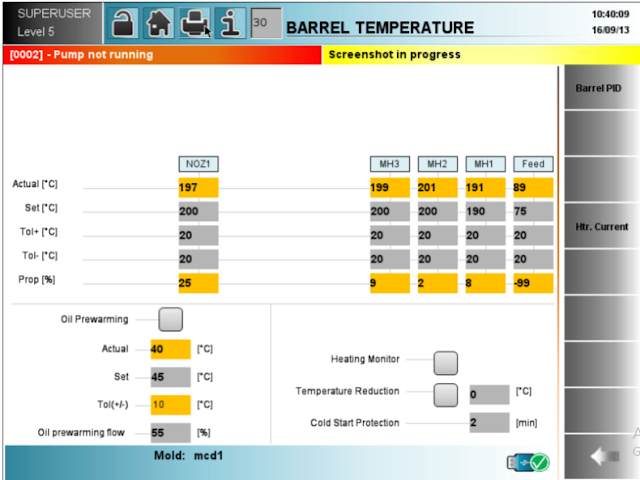
   The barrel heating has a soft switch on the IBED for switching it on. Pressing the switch again will switch the heaters off.     Each heating zone has a set value, an actual value, positive and negative tolerances, and an actual percent of utilization.     If the value of zero is set for a particular zone, then that zone is omitted from the monitoring process.     Appropriate positive and negative tolerances can be set quite independently and separately for each zone.     When the tolerance band is re-entered then screw rotation is prevented for the set cold start protection time.   If the temperature rises above the upper tolerance during Automatic operation, then the alarm CYLINDER TEMPERATURE TOO HIGH is set and ALARM PRESENT appears on the top of the screen and heating is switched OFF.     When the temperature sinks to below the lower tolerance, then the machine continues until the cycle is completed (as in semi-a...

INTRUSION IN INJECTION MOLDING

Image
Intrusion   If the intrusion time is set greater than zero, then the screw will be rotated during this time immediately prior to injection. Material will thus be introduced into the mould.     Both pressure and screw rotation speed can be set separately.  Cold Slug Removal  If it is necessary to remove the cold slug from the nozzle before injection, the appropriate selection can be made from the program options together with a time when the slug is to be removed by injection.   Both injection pressure and speed can be set separately.     This operation occurs before injection unit moves forward.           

INJECTION AND HOLDING PROFILE

Image
Injection Profile   The injection profile can be programmed in 6 steps with 5 stroke trigger points.    The injection start position is taken as the current stroke position at that time.    Example Step 1:    Injection from screw stops position to 70.0 mm with speed            30mm/s    Step 2:     With 20mm/s speed upto 55.0 mm    .... and so on as per the profile programmed.    With time dependent switch over to hold on pressure, the actual switch over stroke will be indicated.    With stroke dependent switch over to hold on pressure, it will occur at 5.0 mm.    If steps are switched out, then the next trigger point is merged in its place for injection speed. Therefore the speed value of the last point remains unchanged until switch over to hold on phase. .... and so on as per the profile programmed.    With time dependent switch over to...

PNEUMATIC EJECTORS INJECTION MOLDING

Image
 Start points and stop points for upto 2 pneumatic valves (depending upon the optional available on the machine), can be programmed independently form each other.       The pneumatic valve can be position dependent or time dependent.     Delay time to start blowing is also settable.      Valves can be activated in manual mode by pressing the suitable key for manual operation   NOTE: When the mould starts moving, the valves will be switched off.  Example:   Valve 1 will start blowing when the mould reaches the mould open stop position (selection 1). It stops when the hydraulic ejector reaches back position.   When the hydraulic ejector reaches the forward position valve 2 starts blowing (selection 2) and will continue to blow till the set time is elapsed (selection 4) or till the mould starts closing (whichever is earlier).   When the hydraulic ejector starts moving forward, valve 3 will blow. I...

CORE SETUP PAGE INJECTION MOLDING

Image
   To switch on the core pull control option select the main “Core pulling control”      Depending on the optional available in the machine (see page 01 MACHINE DETAILS), Core 1 or core 2 or all cores can be selected  by selecting “Enable core 1” and “Enable core 2”      Core 1 may also be operated in rotating core mode by enabling the option ‘Rotating Core’ from the drop down menu     Cores movement with safety gate open is available as a selectable option.     For any core operations the corresponding “Enable core.” selection should be enabled.     If only two cores are to be selected, select core 1 and 2.       If any invalid core sequence is selected the message ‘Wrong Core Sequence’ appears. Please check and correct the core sequence.     Any combination of cores can be operated in parallel either during in or out, by enabling the respective selection switch. Please ensure that th...

COMPLETE PROCESSING PAGE OF INJECTION MOLDING MACHNE - 2

Image
           Screw retraction before dosing (%)                * The speed of screw retraction before refill can be set here.   Screw retraction after dosing (%)              If   * This speed setting determines the speed of screw retraction after refill (suck back speed).           Screw retraction after dosing (mm)              * The end position of the screw after retraction is set here.  Dosing stop (mm)                   * The end position of the screw after dosing. This determines the shot weight of the screw after dosing. Dosing volume is a function of stroke in mm.         Screw retraction before dosing (mm)                *The end positio...

COMPLETE PROCESS PAGE OF INJECTION MOLDING MACHINE -1

Image
This page comprises of the most important process parameter. Cycle time Set  The set cycle time acts as a monitoring time for the completion of cycle. If, due to some reason, the cycle fails to complete within the set time, the machine will signal an alarm.  Actual: The time taken by the machine to complete one cycle. The set cycle time should be higher than the actual cycle time.          Cycle time - last shot                     #   The time taken by the machine to complete the previous shot. Useful for checking the effect of a change in the process parameter.         Blocking time                 #  Blocking time starts after the set cycle time expires. At the end of blocking time the machine goes into shut-off mode as per the switch off matrix setting.         Pa...